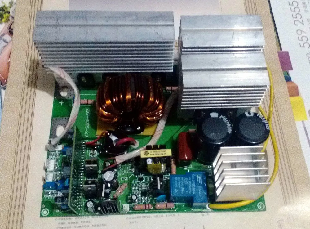
Buy Circuit board ZX7 120 IGBT PCB Single board for
What Is igbt on welding machines Inverter Welders IGBT Inverter Transistor Tokentools These days IGBT on welding machines reffers to the type of transistors used in the inverter matrix that is at the heart of the inverter welding machines operation.

Igbt Inverter Welder Schematic Manual
Table of Contents:. Introduction; UnderstAnding the Function of an InVerter IGBT Welding Machine 2.1 Working of the AC Rectifier Unit 2.2 Testing and Troubleshooting the AC Rectifier Unit; ExpLoring the Output Stage of the Welding Machine 3.1 High Frequency Transformer and Rectifier Unit 3.2 Testing and Troubleshooting the Output Stage; Comparing the Welding Machine with a Simple Mobile.
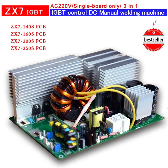
Buy Circuit board of ZX7 250 IGBT PCB Single board for
An IGBT inverter welder is a type of welding machine that uses insulated gate bipolar transistors (IGBTs) to convert DC electrical power into AC electrical power. Unlike traditional welding machines, which rely on large, bulky components to power their arcs, IGBT inverters are smaller and more efficient.

Igbt Welding Machine Circuit Diagram
An IGBT Welder Schematic Diagram is a specialized circuit diagram used to illustrate the wiring connections of an IGBT, or insulated gate bipolar transistor. IGBTs are transistors that control the flow of electricity and are used in welding machines to control the current to the welding electrode.

Verletzen Abdeckung Unendlichkeit inverter welding machine circuit
IGBT (Insulated Gate Bipolar Transistor) inverter welding machines are a type of modern machine that makes use of advanced technology to offer high performance and reliability. In this article, we'll look at the IGBT inverter welding machine circuit diagram and explain how it works.
spot welding circuit diagram
Igbt inverter welding machines are powered by an integrated circuit (IC) that converts direct current (DC) into alternating current (AC). This allows for more precise control over the arc, and enables higher quality welds. A circuit diagram is necessary so that the user can understand how the machine works and troubleshoot any problems.

Circuit Of Welding / Igbt Inverter Welder Arc200 Buy Circuit Of
IGBT INVERTER WELDER. ARC Series welding system pdf manual download. Also for: Arc120, Arc140, Arc160, Arc180. Sign In Upload.. clip the electrode and then welding can be carried out by short circuit arc starting. For welding parameters, please refer to 6.3. 6.3 Welding parameters table (for reference only) Electrode dia..

Igbt Welder Circuit Diagram
What is IGBT Inverter Technology? The acronym IGBT stands for "Insulated Gate Bipolar Transistors". These are high-speed switching devices used in all Weldclass Inverter welding machines which facilitate the voltage regulation. Some inverter machines use older MOSFET technology / transistors.

Igbt Inverter Welding Machine Circuit Diagram
The IGBT, or Insulated Gate Bipolar Transistor, became the most used power electronic component in industrial applications. In the meantime it has become a central component in inverters for all types of electric drives, bat-tery chargers, and solar and wind power plants. But why? What is so special about this component?
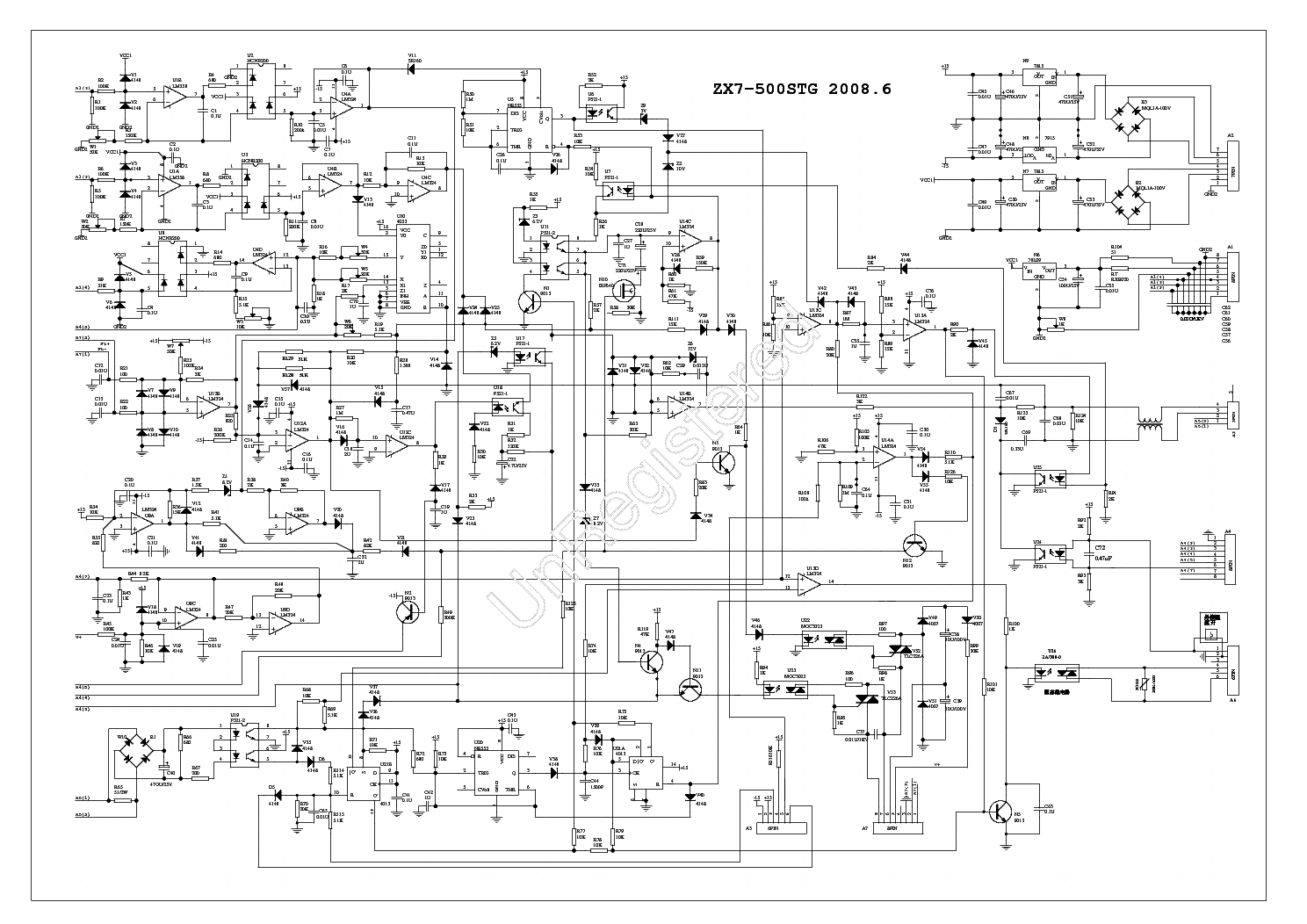
ZX7 500STG INVERTER DC WELDING Service Manual download, schematics
An IGBT welding inverter circuit diagram is a type of welding machine that uses Insulated Gate Bipolar Transistors (IGBTs) instead of traditional transistors. This allows for faster switching speeds and greater control over the welding current, resulting in a more stable and consistent arc. Additionally, IGBT welding inverters are.

Lincoln Electric 225 Arc Welder Wiring Diagram Images Wiring Collection
The arc ignition and welding current are easy to control. The controllable silicon rectifier welder is large and cumbersome, making it inconvenient to move, while the IGBT inverter welder has a small transformer due to the high inversion frequency of 20-30kHz, making it lightweight and easy to move.

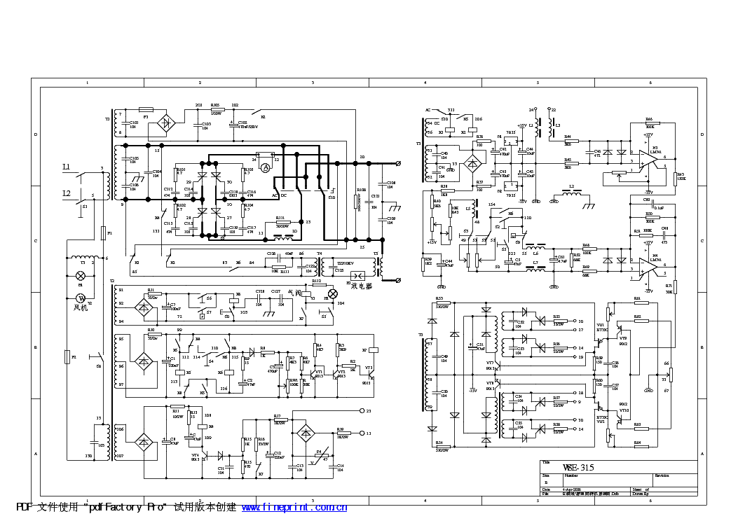
ZX7 315 IGBT inverter welding machine circuit board control panel
From the perspective of power coupling, the MOSFET arc welding inverter can be controlled directly by a microcomputer through the A/D and D/A interfaces, and the control circuit can be simplified, which is the pursuit of modern control circuits. (2) Wide reliable working range. (3) Extremely short switching time.
SMPS Welding Inverter
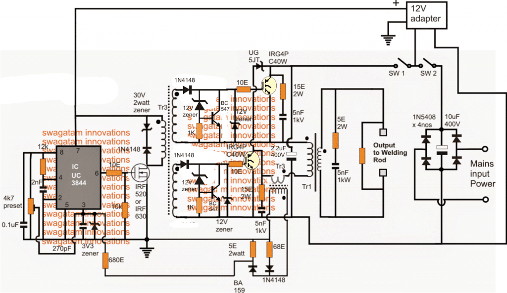
It is a wiring diagram that can help you understand the functioning of an IGBT inverter welder and its various components, such as the rectifier, the transformer, and the DC/AC power supply. This type of circuit diagram is essential for building and repairing IGBT inverter welders.

Igbt inverter welder schematic manual United States manuals Stepby
An IGBT inverter welding machine is a type of welding machine that uses an insulated gate bipolar transistor (IGBT) to convert high voltage, low current input into low voltage, high current output suitable for welding.
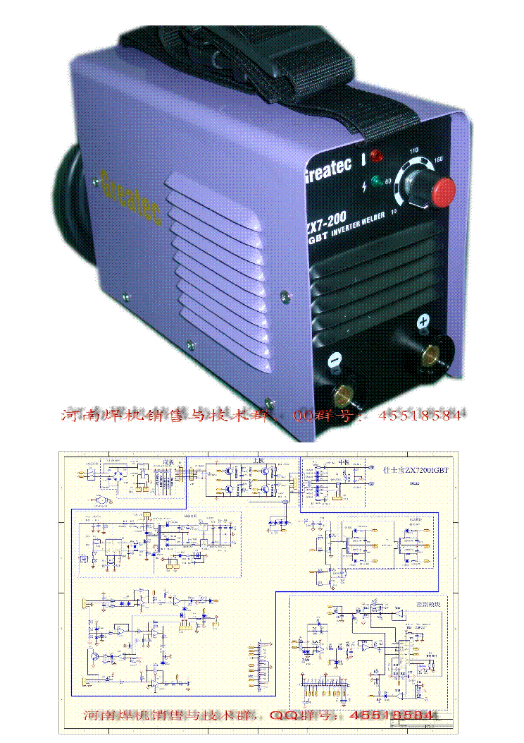
EASYARC ZX7200 IGBT INVERTER WELDER Service Manual download
Two additional control signals are required. Extensions possible for higher level Topology (for I-type) 600V devices instead of 1200V increases Efficiency. Composite Losses - Inverter Mode. ETH-Z (IECON 2010) 650 V, VOutput = 325 V , IOutput = 20.5 A. total Composite Losses - Rectifier Mode.
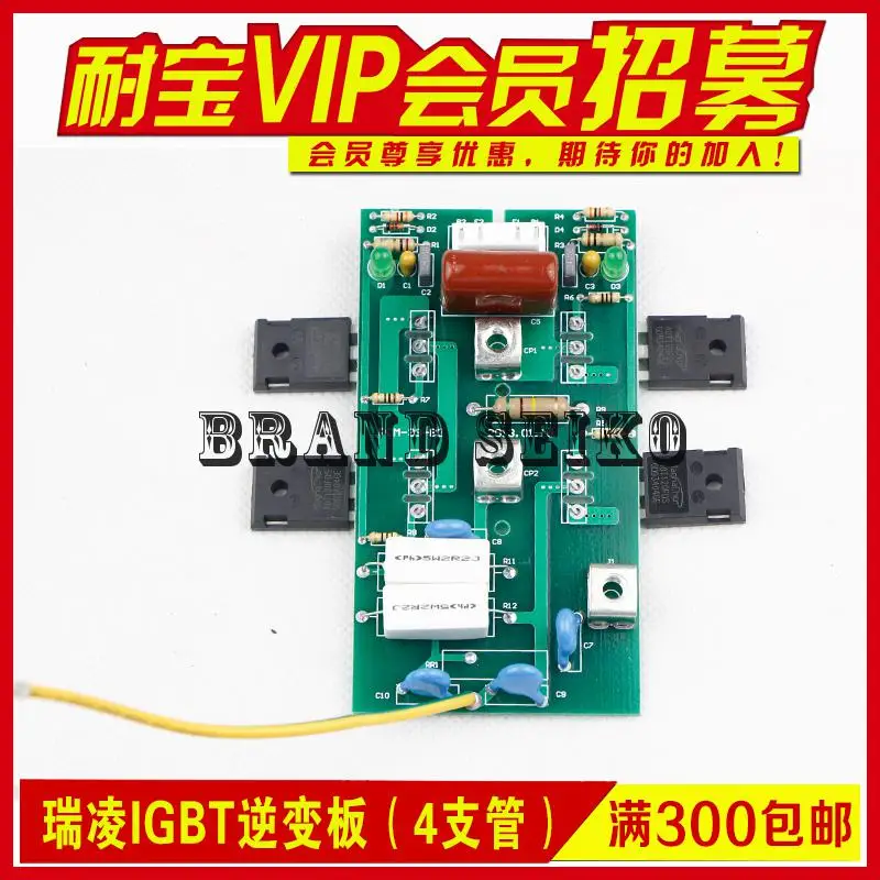
Inverter Welding Machine Accessories Igbt Single Zx7 250 Single Board
An IGBT (Insulated-Gate Bipolar Transistor) inverter welder is a type of welding machine that uses the IGBT technology for efficient and precise welding. The circuit diagram of an IGBT inverter welder is a crucial aspect to understand how the device functions and how different components contribute to its operation.
